|
Z-Way operates on two levels: Every function of the device in the network will be shown as an element. Elements are shown automatically but can be deactivated or hidden. All other functions are realized and managed in apps. These apps can be grouped into four categories.
Some important apps are already pre-installed on Z-Way. Most of the apps are available online on the server and need to be downloaded before they can be used. This chapter gives some examples and recommendations for typical apps available.
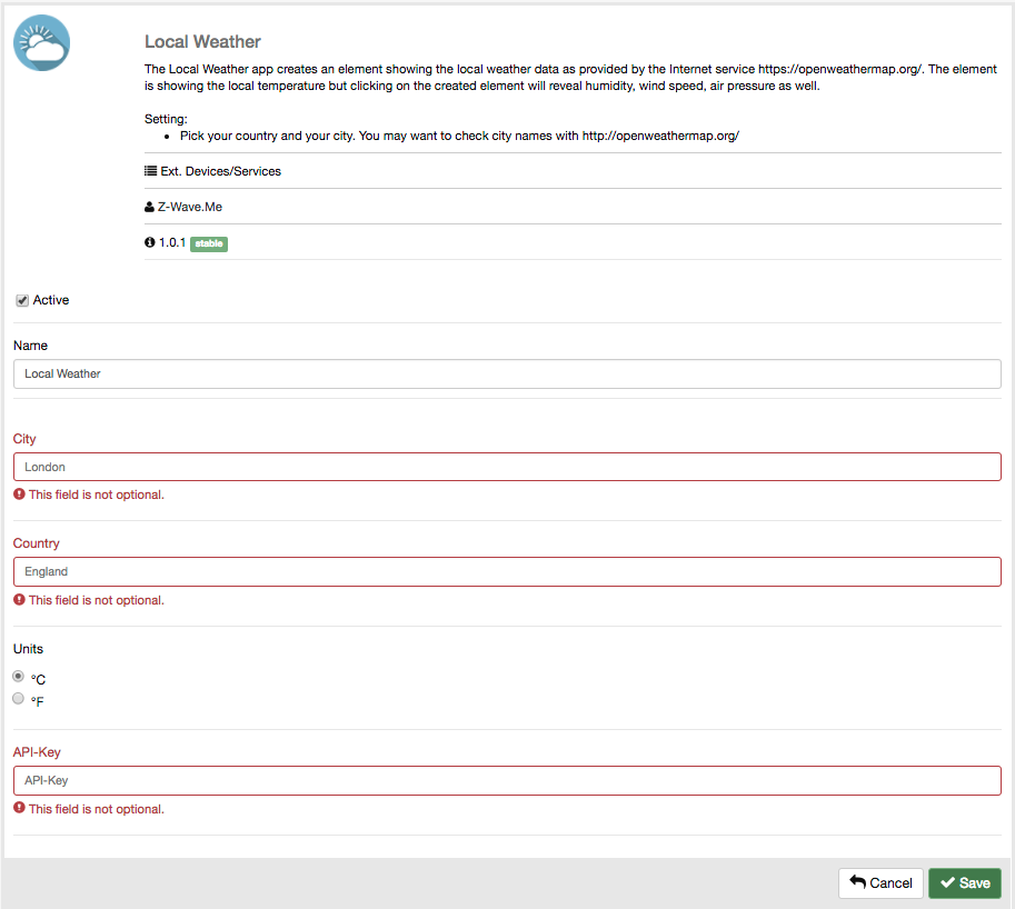
Displaying the local weather inside the smart home user interface is a simple and popular task. Z-Way offers several apps for this request. Already on the device you fine the app 'LOCAL WEATHER' calling data from the known service openweather.org. The data is provided free of charge; however, an API key is needed to access the data. Visit www.openweather.org and register as a user to access your API key. After that, install the weather app 'LOCAL WEATHER' (see Figure 6.1) from the local app repository. Figure 6.2 shows the configuration dialog:
Once activated, a new element is shown on the element view displaying the temperature and the weather situation. Clicking on the small triangle on the right-hand side opens a small window with more weather information such as air pressure, wind speed, relative humidity. The data is updated hourly.
It is possible to display certain values as single element in the element view. This can then be used for automation. Please note, that both the IF and the THEN side of automation like 'IF->THEN' must always refer to active elements. for more information about the 'IF->THEN' app please refer to Chapter 6.2.2.
An interesting app is 'VIRTUAL RAIN SENSOR'. This app creates an app indicating if it was raining on the location. This app sits on top of a weather app and uses their functions and setup. This example shows that certain apps can depend on other apps to be installed first. This concept is known from PC software where certain applications require certain tools or libraries installed first.
Logic or automation is the core of the Smart Home. It allows doing things automatically depending on certain conditions.
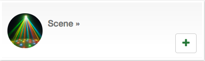
The most basic step to simplify life is to group multiple actions into one action. There is no need to have a smart home controller in the home to do this. Even classical electrical wiring allows switching on two lights with one switch. However, smart home allows creating much larger actions just triggered with one (virtual or real) button. The tool for this is called 'SCENE' and the app is shown in Figure 6.3.
The configuration of the scene app is quite straightforward. All devices to be controlled with the “one button’’ need to be identified and their desired switching status defined.
The scene itself becomes a virtual device, which is why it is also possible to create a hierarchy of scenes and to let one scene switch the other scene.
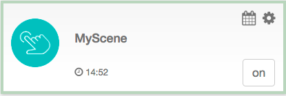
Once stored, there is a new element with the name of the scene as shown in Figure 6.4. There is only one button to turn on the scene. A scene can never be turned off but only replaced by a different scene. The reason for this is that it is not reasonable to turn back to the previous state, since individual devices of the scene may have been operated in the meantime. The scene element shows the time stamp when this scene was activated the last time. The event history shows all the events (activations) the scene, much like how it is done on any other Z-Way actuator.
An enhancement for the scene app is the 'SCHEDULED SCENE' or 'SCHEDULE', as shown in Figure 6.5. This app combines the scene function with a simple weekly calendar that allows executing the scene at a special time per day.
The most basic relationship of automation is the If->Then relationship
IF button 2 on the remote control is pressed, THEN the ceiling lamp will turn on. IF temperature sensor goes above 22oC, → THEN turn down the heating AND open the window.
In order to accomplish this kind of IF → THEN relationship the following requirements need to be met:
The first requirement is quite obvious. If the ceiling light—to stay in the first example—is turned on, the ceiling light needs to be controlled by a wireless device that can be turned on and off wirelessly. While this sounds straightforward, there are plenty of examples where the actor is not able to fulfill the desired task, e.g. a dimming device cannot change the color of an LED light.
The second requirement is also obvious. There must be a defined event that causes an action. In case a button of a controller is involved, this is quite easy, but for sensors that measure constant values, this may become a challenge.
Binary sensors such as door sensors or motion detectors generate an event whenever their binary state changed from on (window open) to off (window closed). For a motion detector, it gets more complicated. The motion part, typically resulting in an ON event is easy to detect but how about the OFF event?
How can a motion detector be sure that there is no person in the room anymore? Most motion detectors allow setting a certain timeout value and generate an OFF event when the time has run out. It is also conceivable to do nothing after a given time. Even then, the motion detector needs to know the minimum time between two events to be generated. Otherwise, it will constantly generate events, resulting in network traffic when a person moves in the room.
Timings and settings are typical configuration values of a motion detector and often can be changed either locally using buttons and/or wirelessly using the Configuration command class described within the Z-WAVE EXPERT USER INTERFACE in Chapter 7.
Sensors that measure an analog value such as temperature, CO2 level, humidity, etc. cannot generate an event from just measuring the value. In case the device is used to start an IF (…) → THEN (…) association action, it needs to know certain boundaries of the measured values and what to do if the measured value reaches the boundary value set. The boundary values that are used to generate events are called Trigger Levels.
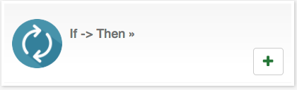
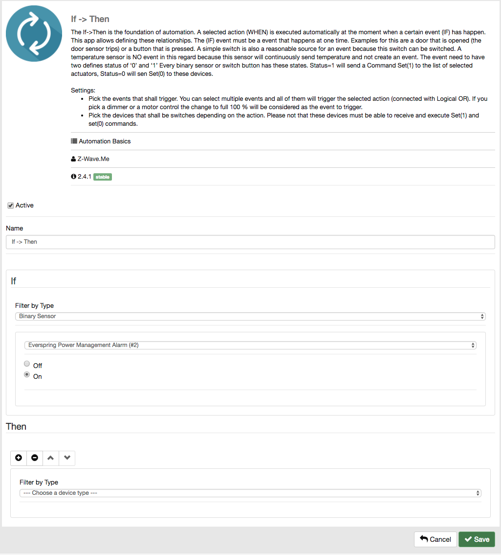
The 'IF->THEN' app, as shown in Figure 6.6, allows implementing the third condition, the relationship between event and action.
Figure 6.7 shows the configuration interface of the 'IF->THEN' app. The first step is to device the event. First, select the device type of the relevant device. This will only shorten the list of devices (elements) to choose next. The device types are
Finally, choose the event that will trigger the 'IF->THEN' rule. For devices with a defined number of states (binary sensor, discrete sensor, binary switch, etc.), reaching this state is the trigger condition. Here it is enough to just pick the state (e.g. off). For analog sensors, it must be defined if the event is reached when the measured value is above, equal, or below a certain trigger value.
Please note that some battery-operated sensors update their value only infrequently. The temperature on a certain spot may rise. Unless the sensor does not transmit this new value, the 'IF->THEN' rule will not kick in.
The second part of the configuration is defining the action. The device and action selection is similar to the IF part. Choose the device type first, then the specific device (element), and finally the action. The selection of device types differs from the IF section for obvious reasons:
Once saved, the configuration becomes active.
One special function of computers in general, and the 'IF->THEN' app in particular, is that it does not necessarily know what the user thinks but what he configures.
Let us take an example: If the relationship is that—IF the door sensor is open, THEN turn on the ceiling lamp—this means that the ceiling lamp goes on when the door is opened. When the door is closed, the ceiling lamp will not go off because this was not written. If the ceiling lamp goes off, a second instance of the If->Then relationship is needed. In case two devices really run synchronously with triggers on and triggers off, another app can realize this step instead of having two times the If->Then app. This app is called is called 'ASSOCIATION.'
'IF->THEN' can connect one event with multiple actions including triggering a scene with even more action. However, it is always one single event. For example, the night light will be turned on by a motion detector but only in the evening and not during the day. This means that different input variables need to be combined to generate the final scene-triggering event. The way this combination is achieved is called binary logic or Boolean logic, and the app implementing this is called 'LOGICAL RULE' as shown in Figure 6.9. Boolean logic has three basic ways to combine variables:
With these three elements, even complex relationships between variables can be described. In case of the evening light triggered by a motion detector, the definition looks quite simple:
It is possible to connect more than two input variables using Boolean logic. However, some constrains need to be considered.
A combination of variables therefore always has one single event but is not a limited list of other status values. Status values are “after 17.00’’ (not right at 17.00, this is an event), a certain switching state of a switch (not the change of the switching status, this is an event).
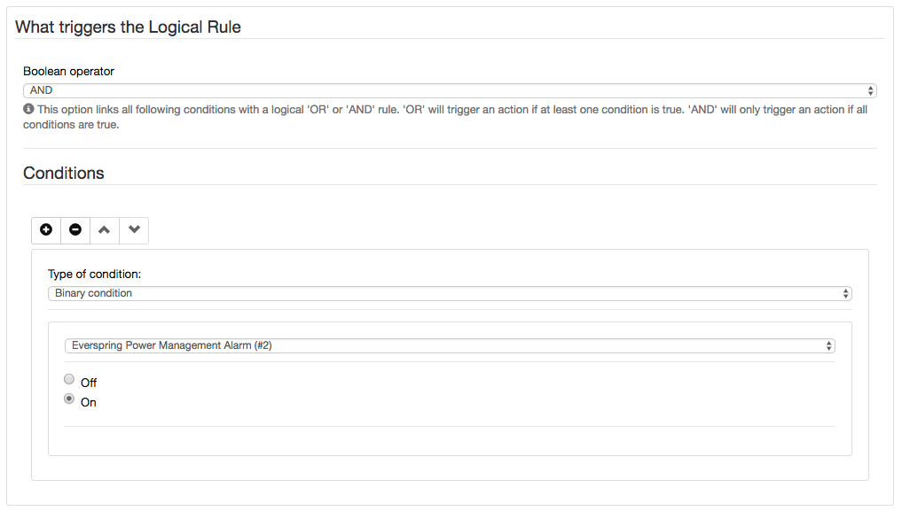
Figure 6.10 shows the configuration of the 'LOGICAL RULE.' The first section allows defining certain conditions (status or events) and defines if all of them (AND) or just one of them (OR) will trigger the rule.
A condition can also be the result of another combination of statuses and events. This is called “nested condition,’’ which allows building a hierarchy of conditions and combining them in any possible way.
The action section is already known from 'IF->THEN' of from scenes. The third section, “How the Logical Rule is triggered,’’ allows some runtime optimization. By default, any changes in the devices mentioned in the rule will have the chance to trigger the entire rule. For very large rules, this may consume a lot of power. That’s why it is possible to limit the number of devices that can trigger the rule. This saves computing power.
Besides the apps 'SCENE,' 'IF->THEN,' 'LOGICAL RULE,' and 'SCHEDULE,' there are a number of other apps in the app store for special automation functions. One little utility is worth mentioning—the dummy device shown in Figure 6.11.
The dummy device creates a virtual switch or dimmer that is shown as an element but does not have any physical function. Nevertheless, it is a valid source of events and status information as well as a valid device to be controlled by scenes. Sometimes, this is helpful to visualize certain situations in the home.
While automation apps are more or less a toolbox to implement original ideas of certain automation and dependencies, the app store also offers complex apps for certain typical functions in the smart home that are already finished and need configuration only.
The leakage protection collects all information from leakage sensors in the smart home and generates one single element to visualize the status of the home. Additionally, the alarm condition is communicated out-of-band. The app needs to be downloaded from the online server, as shown in Figure 6.12.
The configuration allows picking all flood sensors in the home to trigger an alarm. In case of an alarm, certain actions can be triggered. The most obvious action would be to turn off the water supply using a Water Shut Off valve. Additionally, it is possible to send out a notification. A drop-down list allows picking the desired notifier (email, push, SMS, whatever is installed) and define the message to send.
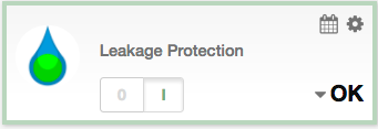
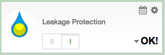
The app creates an element to control the leakage alarm. The element allows arming and disarming the system. See Figure 6.13 for the element when in the armed status. In case one of the flood detectors detects a leakage, the app will go into the alarm state:
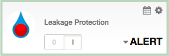
In case the alarm condition disappears (no water anymore), the alarm condition is revoked, but the element will show that there was an alarm event. This indication is shown in Figure 6.15.
The fire protection collects all information from smoke detectors in the smart home and generates one single element to visualize the status of the home. Additionally, the alarm condition is communicated out-of-band. The app needs to be downloaded from the online server, as shown in Figure 6.16.
The configuration allows picking all smoke detectors in the home to trigger an alarm. In case of an alarm, certain actions can be triggered. The most obvious action would be to turn on all lights and open the door. Additionally, it is possible to send out a notification. A drop-down list allows picking the desired notifier (email, push, SMS, whatever is installed) and defines the message to send.
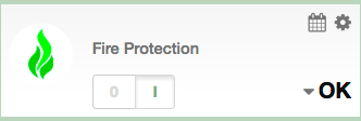
The app creates an element to control the fire alarm. The element allows arming and disarming the system. See Figure 6.17 for the element when in arm status. In case one of the smoke detectors detects a leakage, the app will go into the alarm state:
In case the alarm condition disappears (no water anymore), it is revoked, but the element will nevertheless show that there was an alarm event.
Security is one of the most frequently used functions of the smart home. The smart home can replace the traditional alarm system and implement the function using dedicated devices or reusing other devices such as e.g. motion detectors that were primarily installed for different reasons.
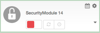
The app 'SECURITY MODULE' implements a complete alarm system with all the functions known from conventional alarm systems. The app must be downloaded from the online server, as shown in Figure 6.18.
The configuration interface allows managing different lists of devices:
The last section of the configuration allows defining time-driven arming and disarming of the system.
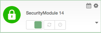
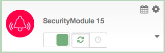
The security app creates an element to control and manage the alarm system. The element allows arming and disarming. Figure 6.19 shows the alarm system in the disarm state. Once armed, the icon turns blue for some seconds, indicating that the alarm is turned on but the alarm system is not yet fully armed. This is important as it allows users to leave the home after they have armed the system. Any sensor in the list of triggering devices will put the system in alarm state once triggered. This results in
Even if the triggering sensor goes back into the non-triggering state, the alarm conditions remain active. The alarm must be cleared by one of the devices configured or clicking on the alarm clear button (two arrows). The system then goes back into the arm state, as shown in Figure 6.20. The clock icon will activate the time-driven arming and disarming of the alarm system.
Saving energy by having intelligent heating and climate control is one of the core values of the smart home. Of course, it is possible to directly control thermostats, but the 'CLIMATE CONTROL' feature manages the whole home and offers a lot of options.
The app must be installed from the app store as shown in Figure 6.22.
The climate app operates on various levels. First, there is a time-driven weekly schedule per room that defines the temperature in that room. The time-driven schedule should be the normal operation mode of the climate control feature. A second layer is the manual overwrite of the temperature. This overwrite can be done on a room layer as well as on the whole home layer.
The first two values are of general nature. The setback temperature is the temperature difference between the comfort temperature in a room and the energy-saving setback temperature in this room. Since different rooms may have different comfort temperatures, the energy-saving temperature also differs but always by the same delta. In case of doubt, please insert 4 Kelvin, which is a commonly accepted value.
The automation reset time defines when the normal automated heating schedule is used again after a manual overwrite of this schedule. The preset 2 hours is a good value.
Now there is a list of rooms. Just add your rooms you want to have the climate control feature. Per room you can define a temperature sensor that shows the temperature in this room in the climate control user interface. There is no further function of this sensor than showing the value in a convenient way. Please note that the dropdown list will only show temperature sensors that are assigned to this room. The comfort temperature is the room-specific temperature. Usually it is higher in bathrooms than in sleeping rooms. Your individual preference matters here.
The last section of the configuration dialog is the heating schedule. It allows setting a temperature at certain time slots on certain days per week for certain rooms.
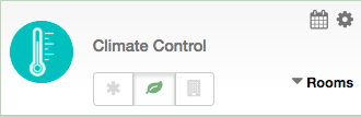
As shown in Figure 6.23, the app generates a special element. It allows running the climate control for the whole home in three basic modes:
 The heating in the home
is turned off. This will overwrite all schedules and all settings in every room.
The heating in the home
is turned off. This will overwrite all schedules and all settings in every room.
 The heating in the
whole home is in the energy-saving mode. This will overwrite all schedules and all settings per room.
The heating in the
whole home is in the energy-saving mode. This will overwrite all schedules and all settings per room.
 No home-wide
overwrite. The room-specific settings apply.
No home-wide
overwrite. The room-specific settings apply.
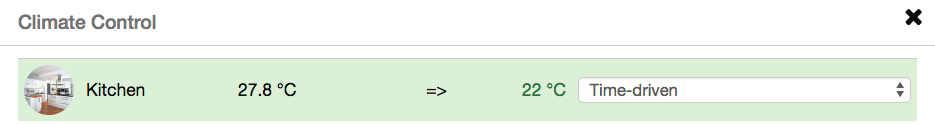
The little triangle on the right-hand side allows opening the room view as shown in Figure 6.24. Here, it is possible to see the actual temperature per room plus the current desired temperature. A dropdown list allows choosing the heating mode for the specific room:
All events in the smart home are shown in the user interface, or they can be indicated using devices inside the home. However, people do not always monitor the user interface. Hence, there are the so-called out-of-band notification options to reach the user in such a case:
Z-Way supports various ways of out-of-band communication. For every communication channel, multiple apps from different providers may exist to realize the same function. However, all these notifiers work in the same manner:
Some out-of-band notifiers make it possible to gather and filter events from the timeline and forward them. This must be configured in the configuration dialog.
Push notifications are delivered to a mobile phone. As soon as one of the native Z-Wave.Me apps is installed on the mobile phone, the push notification option is automatically enabled. Push notifications allow gathering events and forwarding them automatically. This can be configured in the apps 'MOBILE PHONE SUPPORT, NOTIFICATION FILTERING' which is already running in the system. Please go to Active app management to open the configuration dialog.
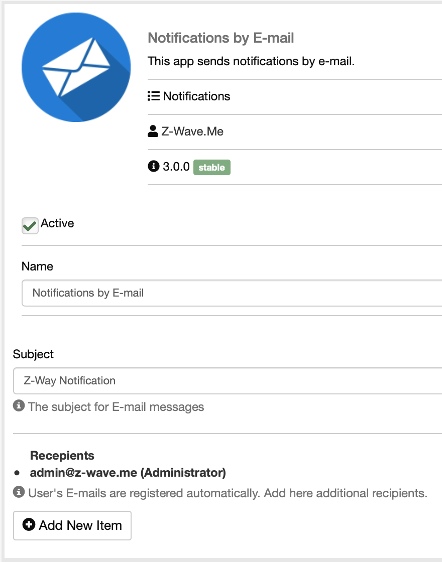
The 'NOTIFICATIONS BY E-MAIL' app, as shown in Figure 6.25, for each user creates a communication channel for sending events by email.
In the 'NOTIFICATION FILTERING' application, you can select the notification channel, it can be email, push, sms or a channel provided by third-party applications: facebook, twitter and others.
Besides the two standard notifiers for push notifications and email, the app store has plenty of other notification apps from third-party developers. Just check out what works for you.
The app store is a gold mine of cool applications. This manual can only mention a few of the more popular ones. Of course, you can check out the display of apps according to popularity, etc.
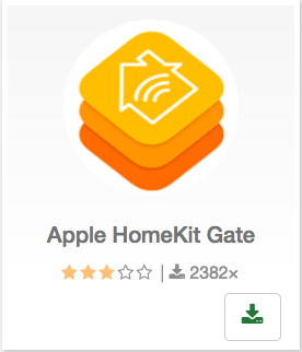
As shown in Figure 6.26, the Apple Home Kit App, provided by a third-party programmer named Andreas Freud, connects Z-Way with Apple’s HomekitWorld. Once installed, the Z-Way controller is shown to Apple as a Homekit bridge device. Please be aware that this app is maintained by a third-party developer and the existence of the apps is certainly not in the main interest of Apple.
This app (Figure 6.27) adds a little icon to the selected device. Clicking on this icon opens a window with a chart showing its history. To use this app, you have to be registered at www.intchart.com. Note that if you change the settings below, the chart can be reset, but the previous chart will still be visible on intchart.com.
The settings are as follows:
This app (Figure 6.28) from Maros Kollar calculates the position of the sun above the horizon for the given location. The module provides various metrics for other automation modules like sun altitude and azimuth, and emits events when the sun reaches certain positions. This module can be used to control light scenes or shading based on the solar position.
Check github.com/maros/Zway-Astronomy for detailed documentation.
This app in Figure 6.29 integrates Z-Way with the Amazon Alexa Voice Control system. Once installed, you need to activate the “skill’’ in the Alexa user interface before using.
HUE is a new way to use your Philips Hue SmartHome solutions. Use this app (Figure 6.30) as a remote to switch colors, turn up the brightness, and quickly toggle between lights on and off. For the moment, you have to create your credential manually.
Installation instructions:
To create your own key, see more details on:
Apps for developers require a certain amount of programming skills and partly require knowledge about the Z-Way data model. Please refer to Chapter 11 for details.
Nevertheless, the app 'HTTP' device allows adding certain functions without deep software knowledge. The 'HTTP' device generates a sensor or an actor depending on information obtained by just accessing a website using HTTP.
One example will demonstrate this. The goal is to make an element that shows the current USD/EUR exchange rate. The website
http://api.fixer.io/
offers this data free of charge. Even more conveniently, the URL
http://api.fixer.io/latest
delivers information in a machine-readable JSON format (you can use the URL in a standard web browser to have a look at the structure.)
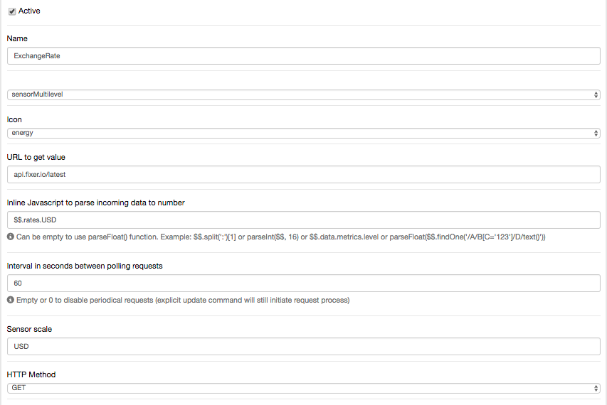
In the http device configuration, a multilevel sensor is chosen, since only values have to be shown and they are not only 0 and 1. Then the URL api.fixer.io is provided (attention, without http!). This will now call the whole JSON data set. For the element, the right value needs to be extracted. Here some JavaScript knowledge is needed to understand the command
“$$.rates.USD.’’
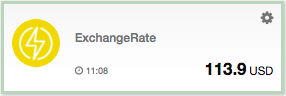
Finally, the refresh rate is defined and a nice name given. The other form elements are not needed here. After saving the configuration, the new element is visible. A little optimization is to show the cent value by changing the JavaScript into
“parseFloat($$.rates.USD)*100.’’
The sensor based on the exchange rate can now be used like any other analog sensor. Setting a trigger on certain exchange rates may be used to activate a special scene. Indeed, this is more for day traders on EUR/USD exchange, but may still be cool.