|
The Z-WAVE EXPERT USER INTERFACE is designed for installers, technically savvy people, and other users that know how to build and maintain a Z-Wave-based wireless network. Hence, it uses some Z-Wave specific-language and offers detailed insight into the work and data structure of the Z-Wave network. It allows users to:
Besides the menu items, there is a configuration setting (wheel icon), a time indicator showing the time at the time zone of the gateway and a job queue indicator. Clicking on this job queue indicator opens a new tab displaying the job queue of Z-Way. Please refer to Chapter 7.8 for more information about the job queue.
All values shown in the Z-WAVE EXPERT USER INTERFACE are assigned to a time stamp indicating when the value of status information was received from the wireless network. A red color of the time stamp indicates that the update request from the controller to the device for this value is pending.
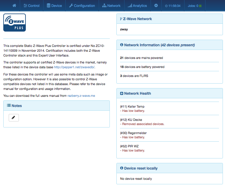
The home screen shown in Figure 7.1 offers some high level of information about the software and a notepad where the user or installer can leave important information for future use.
The section 'Network Information' box offers some statistics about the number of devices in the network and how many of them are mains or battery-operated. The network health box will list devices that have problems:
Clicking on the statement will lead to a help page explaining the problems and giving guidance for remediation.
The last infobox will contain information about devices that were removed using the device reset function. In this case, the device will leave the network but informing the controller. There is no exclusion process applied.
The tab Control allows operating the various types of device and shows the reported values in case of sensors or meters. In case the control options offered here are not sufficient, please refer to Configuration > Expert Command for a full set of functions supported by the device.
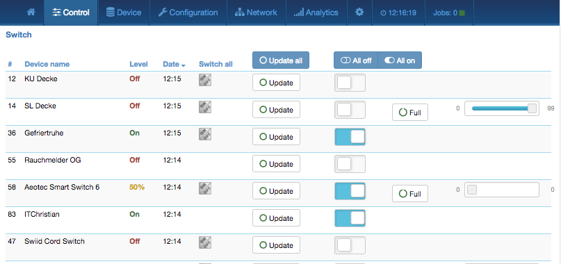
The switch dialog shown in Figure 7.2 lists all devices of the network supporting switching, dimmer, or motor control capabilities. The device name and Z-Wave ID, as well a the current status of the switch, are given and the time of the last status update. The Update button forces an immediate update of the switch (if mains powered device). A 'Switch All' Icon shows whether or not the specific device will react to a All ON or All Off command. A green triangle indicates that the device will react to the command shown. All actuators can be switched on or off. Dimmer and motors controls can be operated using a slider. For dimmer, there is a button On and Full. Full turns the dimmer always to 100 %, diming value while On turns to the last dimming state before the dimmer was turned off. Clicking on the table heads reorders the table view of the data.
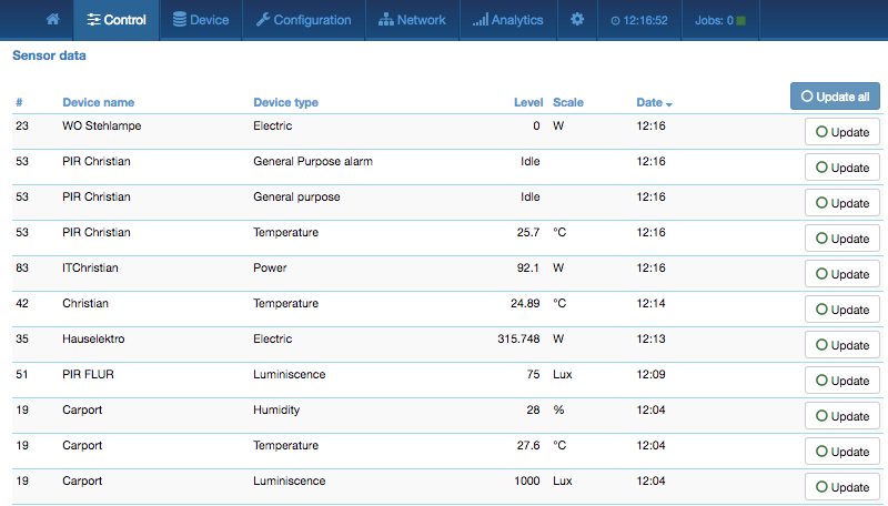
The sensor dialog shown in Figure 7.3 lists all devices of the network providing sensor information. Device name and ID, the type of the sensor, the actual sensor value and the sensor scale is listed. The date/time column indicates when the given sensor value was received. It’s possible to call for a sensor update but bear in mind that battery-operated device will only respond after the next wakeup.
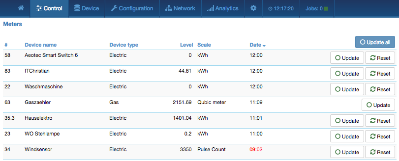
The meter dialog shown in Figure 7.4 lists all devices of the network providing (accumulating) meter information. Device name and id, the type of the meter, the actual meter value and the meter scale is listed. The date/time column indicates when the given sensor value was received. It’s possible to call for a meter update but bear in mind that battery-operated device will only respond after the next wakeup. Clicking on the table heads reorders the table view of the data. A meter reset button is shown for device supporting this function.
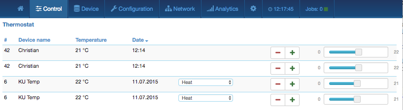
The thermostat dialog shown in Figure 7.5 lists all thermostat devices of the network. Device name and ID and the current set point temperature is shown. The date/time column indicates when the given set point temperature was transferred to the device. The set point temperature can be changed using the + or - buttons or the slider. Clicking on the table heads reorders the table view of the data.
Some thermostats may offer different modes such as heating, cooling, off, etc. For these devices, a drop-down list shows all modes available. In this case, the setpoint is only valid for the mode selected.
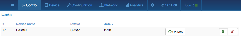
The door lock dialog shown in Figure 7.6 lists all door lock devices of the network. Device name and ID, the current status of the lock, and the last time of the change of the status are listed. The lock can be opened or closed. Clicking on the table heads reorders the table view of the data.
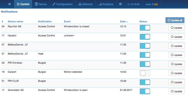
The notification dialog shown in Figure 7.7 lists all notification devices. Notification devices act like binary sensors, albeit offering some more capabilities. Per notification device multiple events can be reported. The notification device also allows deactivating the notification for certain events. Please note that not all devices make use of these functions.
The menu Device gives access to overview pages with more detailed information about the devices in the network and their actual status.
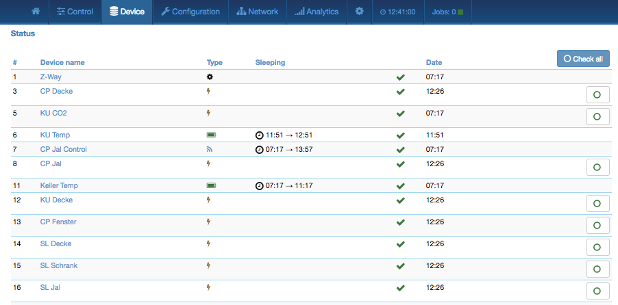
This dialog in Figure 7.8 shows the actual network status of all devices. All devices are listed by their node ID and name. The date/time indicates the time of the last successful communications between the controller and this device (either confirmed sending or reception). The green checkmark indicates that the device is alive. A red sign indicates that the controller assumes the device not being active anymore. Mains powered devices can be checked for their network availability by hitting the o button on the right-hand side.
In case the device interview and configuration were not performed properly, a little
question mark icon will indicate this. Clicking on the question mark will open a window
displaying the details of the interview process.
The correct loading of a Device Description File![[*]](footnote.png) is indicated as
well. For a battery-operated device, the time of the last wakeup, the time of the
next wakeup, and the current wakeup status are shown. Clicking on the table heads
reorders the table view of the data. Clicking on the table heads reorders the
table view of the data.
is indicated as
well. For a battery-operated device, the time of the last wakeup, the time of the
next wakeup, and the current wakeup status are shown. Clicking on the table heads
reorders the table view of the data. Clicking on the table heads reorders the
table view of the data.
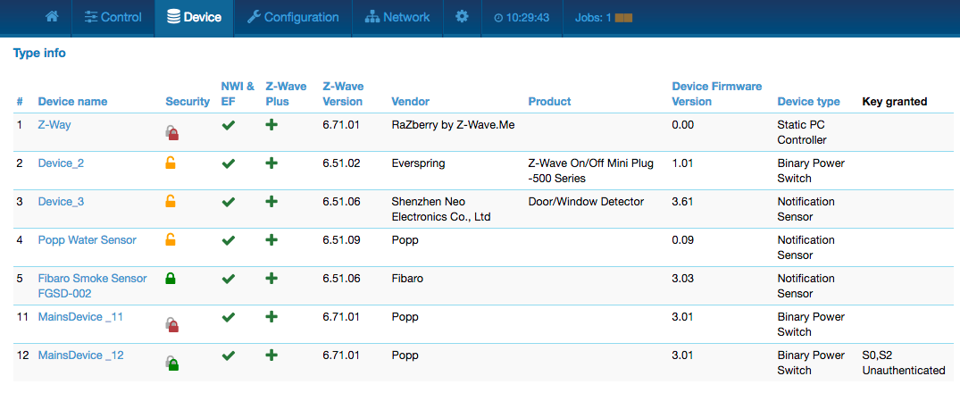
The type info dialog shown in Figure 7.9 lists all devices of the network and indicates if they support enhanced Z-Wave functions such as Security and Z-Wave Plus. Additionally, the Z-Wave protocol version, the application version and the device type indicator of the device is shown.
The security icon determines what kind of security the device supports:
 : Device does not support any security class
 : Device supports security version 1
 : Device supports security version 2
 : Device supports security version 2 but authentication failed
The last column shows the security keys granted for the device.
Clicking on the table heads reorders the table view of the data.
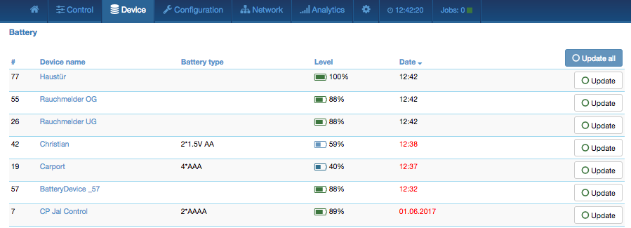
This dialog shown in Figure 7.10 gives an overview of the battery status of the battery-operated devices in the network. Devices are listed by name and id. The last reported battery level (0–100 %) including update time is shown as well as the number and type of battery if known. The Update All button will request a status update from the device. The new status will be available after the next wakeup of the device. Clicking on the table heads reorders the table view of the data.
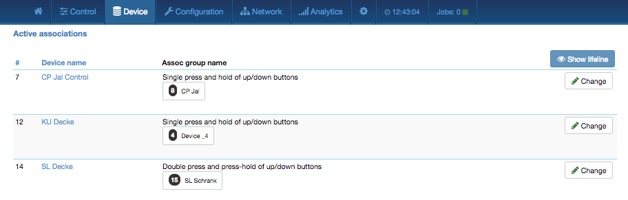
This overview page shown in Figure 7.11 lists the current association set in the network. The Lifeline is an association to the gateway to report status changes and heard beat and can be hidden if needed. A Change button leads right to the configuration page of the device to change association settings.
The tab Configuration allows configuring the functions of a particular device. Pick the device to be configured from the drop-down list or pick the device from the full list shown on the left-hand side. The functions of the device are grouped into 6 tabs.
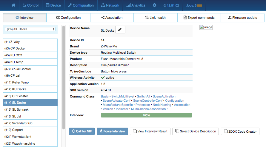
Configuration > Interview, as shown in Figure 7.12, documents the result of the device interview. In this process, the controller tries to get information about the device. In case the controller finds a device description record for the device, it will display further information about the device that cannot be obtained from the device itself:
If the software will not automatically recognize the device and load the description record a button Select Device Description Record allows doing this manually. However, the description file must be present. Chapter 13.5 gives further information on how to create an own Device Description Record and load it into Z-Way.
The interview stage line gives information about the progress of the device interview.
There are a few reasons why an interview is not complete: In most cases the devices went to deep sleep too early to have some wireless connectivity problems. The button Force Interview allows re-doing the whole interview. The button Call for NIF requests a Node Information Frame from the device and the Button View Interview Result allows displaying the information about the different command classes found during the interview. It is also possible to force the interview of a certain command class only.
The button ZDDX Code Creator allows creating an XML description file usable for certain device databases.
The only configuration option on this tab is to change the given name of the device. During inclusion, the software generates a generic name, but it is highly recommended to change this name. The given name should be descriptive but not too long.
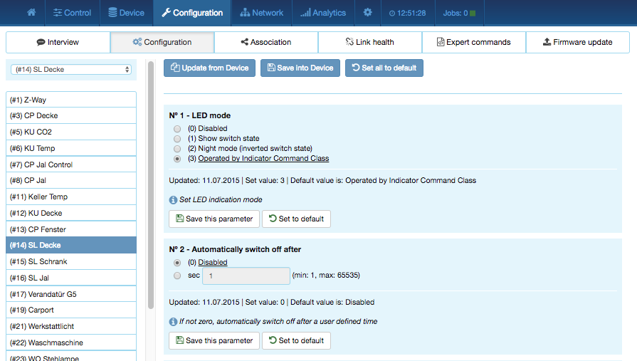
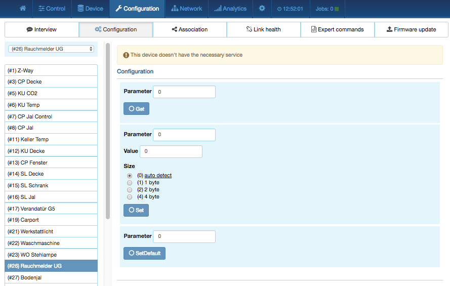
Configuration > Configuration shown in Figure 7.13 allows configuring the device. If the specific device was recognized correctly the different configuration values are translated into human-readable dialogs. Every configuration comes with standard dialog options:
If the device is not known (means there is no Device Description File assigned to it) it is still possible to set configuration values. Figure 7.14 shows the generic configuration dialog used in this case. The specific configuration parameters and its values need to be read from the device manual.
There are four more command classes that may need additional configuration and are displayed in the same dialog if the device supports them.
Note: For mains-powered and FLIRS devices, the button Save this parameter or Save into Device will activate the changes within few seconds. For battery-operated devices, the commands are stored to the next wakeup. It’s possible and recommended to wake up the device manually to speed up the change of configuration values.
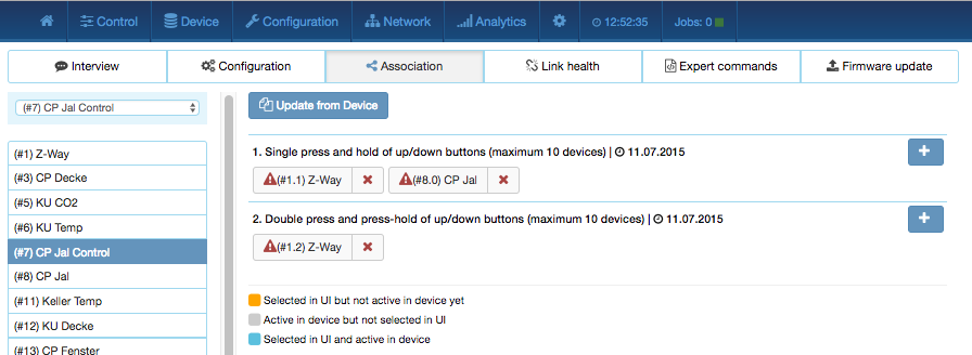
Associations allow switching a Z-Wave Device B (target) as a result of an event in Z-Wave Device A (source). Z-Wave Device A manages a list of devices to be controlled for each event supported. The device list associated to a specific event—also called association groups—and the devices that are associated with it are shown in the association tab in Figure7.15.
In case the information is provided either by the device or by the device record stored in the software, the meaning of the events is written. Otherwise, the event group is shown unnamed as number only. In this case, refer to the devices manual for more information about the association group meaning.
The stored devices can be called from the actual device using a button. The buttons +/- used to add and remove device from the group. A dialog is opened and a device can be picked. In case this device has multiple instances, an instance drop-down list will appear allowing to choose the right instance of the target device. The node ID and—if applicable—the instance ID are shown in the target device list. Move the mouse over the ID to show the complete given name of this device. The color of the device name or ID indicate the status of the association entry:
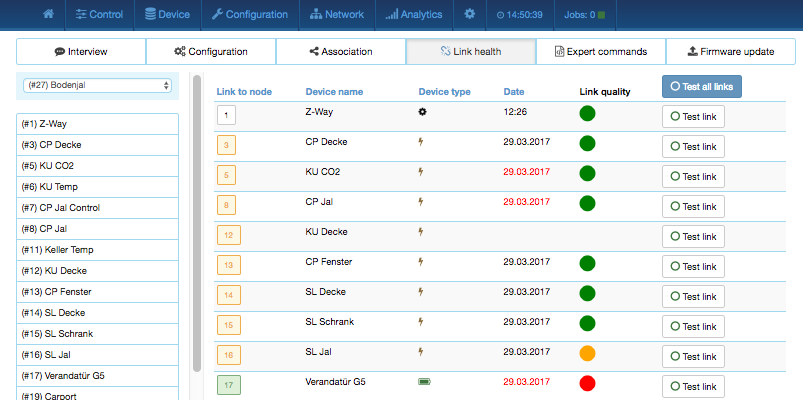
Modern versions of Z-Wave allow testing the quality of a link between two devices in direct wireless range. The dialog shown in Figure 7.16 lists all devices in wireless range and gives an indication about the quality of this link. The following colors are used:
Individual links can be retested using the Test all links button. It is also possible to test all links from a given device. However, please keep in mind that this process may take several minutes to complete.
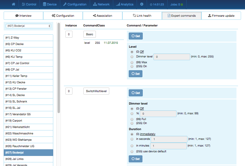
Configuration > Expert Commands as shown in Figure 7.17 displays the status values and possible commands in a very generic way. On the left-hand side, the different instances (channels) of the device are listed in a column. In case there is only one channel (that’s the case for most devices), only channel/instance 0 is shown. Clicking on the number opens a dialog showing all internal variables for the channel. The next column shows all the command classes exposed by the device. Again, clicking on the name opens a dialog with more internal status variable information for this command class. On the right-hand side, there is a list of commands. This dialog form is auto-generated from the information provided by the command class itself and not optimized for daily usage.
In case the device supports a firmware update “over the air,’’ this dialog is shown to perform such a firmware update. The firmware file to be uploaded must be available in a raw “BIN’’ or the Intel hex “HEX’’ file. The target field allows specifying the target memory/processor for the update process. For updating the Z-Wave firmware part a “0’’ must be set. The firmware updating process will take up to 10 minutes. Please don’t do any other operation during this time. It may be required to activate the firmware update mode on the device to be updated. Please refer to the manual for further information about activation.
The network section of the user interface focuses on the network as such and offers all controls and information to build, manage, and repair the wireless network of the controller.
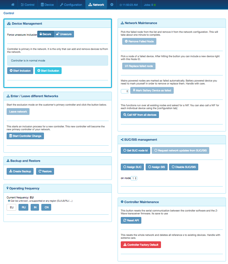
Network > Control summarizes all commands needed to manage the network and the controller. The page is structured in four boxes.
The device management box as shown in Figure 7.18 allows including and excluding Z-Wave devices. A status display shows the status of the controller. The Include Device and Exclude Device button turn the controller into the Inclusion and Exclusion mode. In this case the status display changes and the resp. buttons turns into a Stop function. The inclusion and exclusion modes will time out after about 20 seconds but can always be terminated using the Stop buttons.
Another way to stop the inclusion mode is to actually include a new device. In this case the inclusion mode will stop and the node ID of the new device is shown. The controller generated a default name of the device as combination of its primary function and the new node ID. Clicking on this default name leads to the Configuration page where the name can be changed and other configuration tasks can be performed.
Please refer to the devices manual on how to do an inclusion. In case the inclusion does not work as expected, please exclude the device first. More than 90 % of all inclusion problems are caused by still included in a different network and can then not being included again.
The Exclusion mode also stops when one device was successfully excluded. This function can exclude devices from other networks too but the device need be available and functioning. To remove nonfunctioning or disappeared devices please refer to Replace Failed node or Remove Failed node.
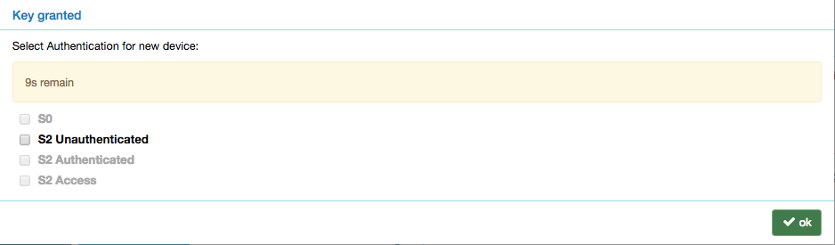
In case the new device supports enhanced security function (Security Command Class), this controller will include the device securely. After this all data exchange between the controller and the new device is encrypted using AES encryption. For performance reasons, it mays be desired not to use the security function. The slider Force unsecure inclusion turns the controller into a mode where all security functions are suppressed for the included device. Security functions of other devices are not impacted. In case the new device supports Security S2 right after inclusion, a pop-up window will appear asking the user to grant the S2 security keys. A few basics about this process: Security in Z-Wave means among others that all communication between two nodes over the air is encrypted. Encryption however requires a key to encrypt and all the device communicating shall have the very same key—usually called network key. Z-Wave Security 2 handles 4 different network key. They differ by their level of trust.
Each device will request one of more network keys according to the device usage and implementation idea. The default key is likely S2 Authenticated but Door Locks will ask for S2 Access control and small devices without external label request S2 Unauthenticated only. Figure 7.19 shows the dialog to grant the keys. The requested key is displayed in bold letters. The user has 20 seconds to select the keys to be granted. If no selection is made with 20 seconds, the process will time out and the device is included unsecure. Please note that some devices may still offer valid functions while other will deny any function outside a secure environment. It is recommended to grant the keys requested, but there may be certain environments where other selections may make sense.
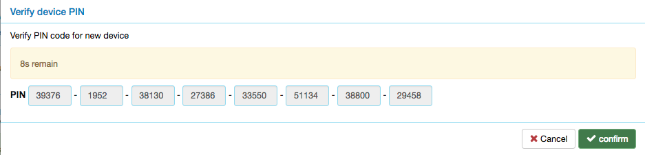
Once the selection is made before timeout a second window will request the authentication of the device. In case of S0 or S2 Unauthenticated, the window displays the device-specific key for information only as shown in Figure 7.20. If a key is visible on the device, it is recommended to compare the numbers. However, the key is granted without any further interaction by the user.
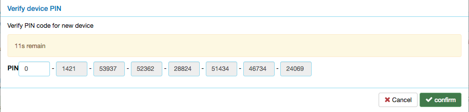
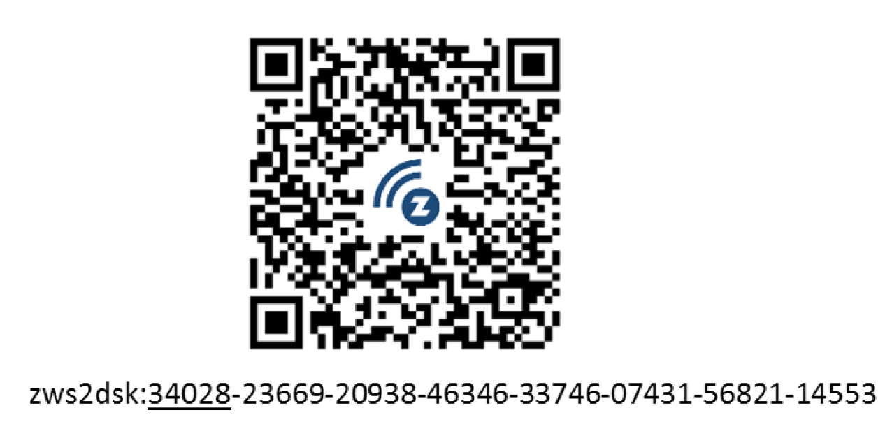
In case S2 Authenticated or S2 Access Control keys were requested the dialog windows asks for providing the Device information by the user. This can be done by typing in the 5-digit PIN code (first 5 numbers of the device-specific key) as shown in Figure 7.21 or by scanning the QR code on the device shown in Figure 7.25.
In case of Access or Authentication, the user must insert either a PIN number or scan a QR code from the device just included. This insures 100% that the device just included is really the device in hand. If authentication fails, an error message is displayed. It is not possible to redo the key authentication only. You must exclude and re-include the device.
Smart Start is a new way to include devices into Z-Wave using the QR code provided with S2 authentication. The user scans the QR code thats is stored in an internal so called provisioning list. Smart Start Devices will then announce to be included when powered up. In case the S2 key is in the provisioning list the controller will automatically include this new device without any further user interaction.
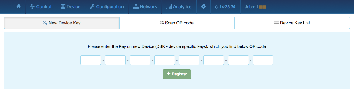
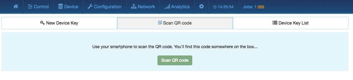
Smart Start is controlled by the button Activate/Deactivate Smart Start. The button Smart Start opens a submenu allowing to register Device keys either by typing the 8 groups of numbers as shown in Figure 7.22 or using a QR code scanner as shown in Figure 7.23. Please note that a standard web browser running on a standard PC may not provide the capability to scan QR codes.
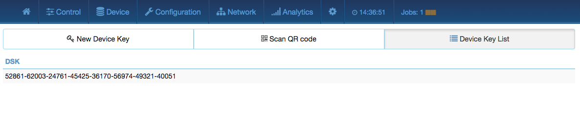
Figure 7.24 finally shows the lost of Device keys already registered in the system and not used. Used means in this context that the corresponding device was powered up in proximity of the controller and got included automatically. Please note that the Razberry Shield or UZB or any hardware used must provide a firmware with SDK >=6.81. Otherwise Smart Start will not work.
This button will only be active if Z-Way is in factory default state. Only in this case the controller can be added to a different network as secondary controller. The controller of the other network must be in either the Inclusion or in the Exclusion mode, and the Learn button confirm the process.
In case the new primary controller supports Security S2 a dialog window will pop up right after finishing the inclusion by the new controller. This dialog window will show the PIN number and the QR Code of this Z-Way controller needed to authenticate against the new controller.
The Start Change Controller function actively hands over the role of the primary controller of the network to a controller that will be included using the normal inclusion process. The controller status dialog shows the mode and its termination.
The next dialog box of the page allows creating and using a backup. The backup file is stored on the local computer. Please note that any restore will overwrite the existing network. The restore operation must therefore be confirmed in another message box. A checkbox defines if the node information in the Z-Wave chip itself will be overwritten as well. This operation result in a possible loss of all network relationships and may require a re-inclusion of devices. Handle with care!
The controller maintenance offers two reset buttons. The Z-Wave Chip Reboot restarts the operating system of the Z-Wave transceiver chip. This can be done safely all the time.
The Reset Controller turns the controller back into factory reset. All connections to included devices and all configurations and settings are lost. This function must be handles with extreme case. An additional dialog requires to explicitly confirm the function. Only use this function if you know what you do!
This dialog allows changing the operating frequency. Please note that a wrong frequency will block all Z-Wave traffic and make the device inoperable. Frequencies can only be changed within one frequency group. These are the frequencies shown side by side (e.g. EU, RU, IN, ...). Changing to a frequency outside this group will technically work but the wireless range will be few centimeters only. Hence, this for workbench testing only. The device will reboot after a frequency change so please allow some time for restart.
The function Remove Failed Node allows removing a node that is no longer communicating with the controller. After multiple failed communications with a device the controller will mark this device as failed and avoid further communication. This function finally removes such a device from the network configuration. The drop-down list will only show IDs of failed nodes. If this list is empty this is a good sign!
It is also possible to Replace a Failed node with a new node. This is a combination of removing the failed node and adding a new node. Using this function makes sure the next included node has the same node ID as the failed node. The drop-down list will only show IDs of failed nodes. If this list is empty this is a good sign! Battery-operated devices are mainly in deep-sleep state and will not answer to communication requests. Hence, the controller will never automatically detect if a certain device is defect or gone. The function Mark battery device as failed manually marks battery-operated devices as failed so that they can be removed or replaced. The drop-down list shows all battery-operated devices but this does not mean that they are failed.
The Request NIF from all devices function is just a convenient way to retrieve a Node Information Frame from all devices of the network.
The SUC/SIS Management pane allows manipulating the self-organization of the Z-Wave network. Don’t use this unless you are a developer who knows when and why this is needed for testing purposes.
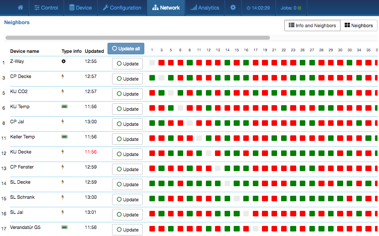
This table in Figure 7.26 shows the neighborhood relationship of devices. The id, the name and the type of the node are listed. Green indicates that the two devices are in direct wireless neighborhoods and don’t need any other device to forward their signals. A red color between two nodes indicated that routing is needed between these devices. The Update button calls the device to scan its neighborhood and report back the result to update its own line of the routing table.
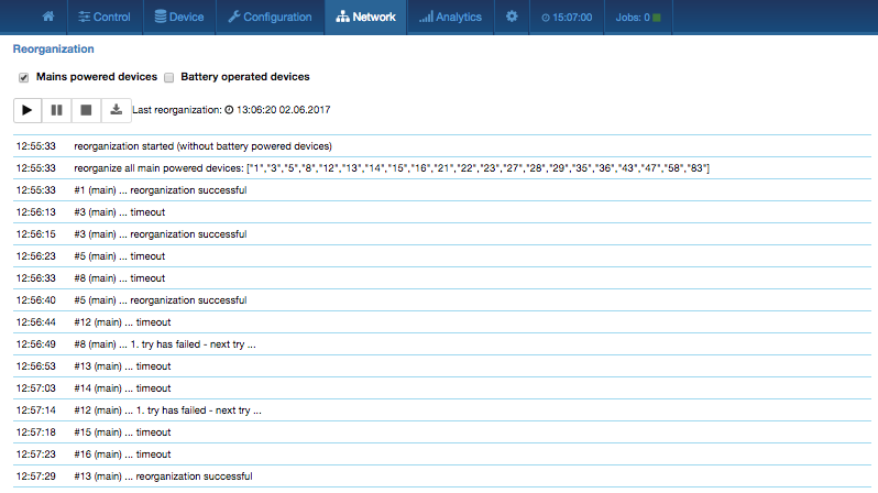
The reorganization page controls as shown in Figure 7.27 an algorithm that reorganizes the network relationships and fixes problems. With checkboxes various stages of the algorithm can be selected. The result of the reorganization is shown in a log and can be downloaded. The network reorganization calls for every node to redetect its neighbors. This operation will work if there is a working route to this device and this device is not sleeping. If the operation fails, the algorithm will have three more attempts to reflect possible routes to the very device that may be reestablished during the reorganization. Detection of neighbors for battery-operated devices will be started after all mains-operated devices are processed. The requests to battery-operated devices will be queued. For more information about job queuing, please refer to Chapter 7.8.
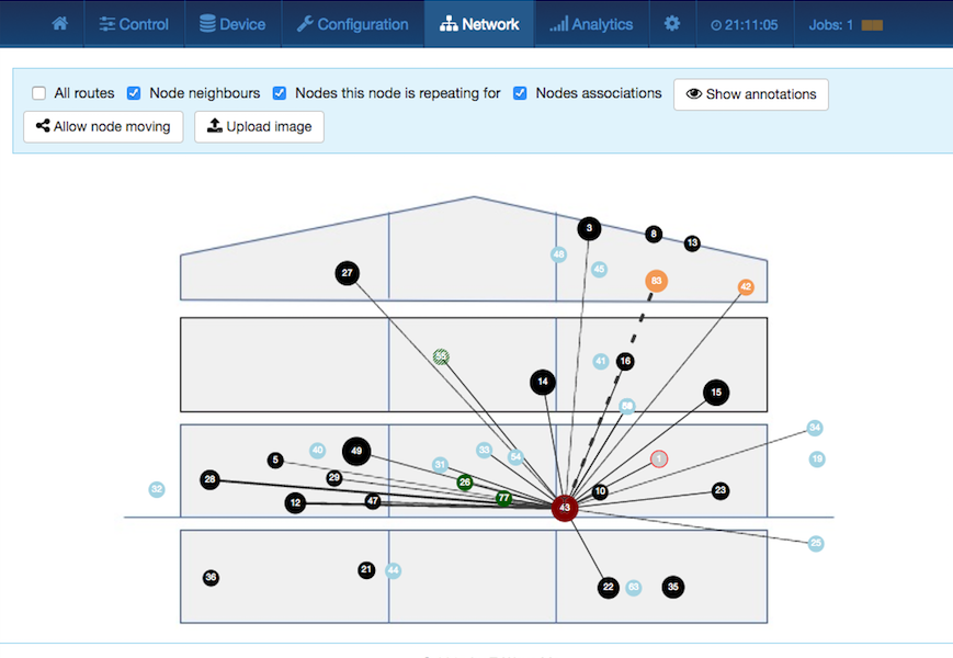
The Route Map is a way to map the network is an extremely powerful, informative but the same time very complex viewgraph of the network situation in a home. The chart visualizes the possible links between the nodes and how they are used. If provided by the devices the chart will furthermore show complete routes and the signal strength of the individual links of a route. However only devices with SDK greater or equal to 6.71 will provide this additional information.
Initially all nodes are displayed with equal distances. It is possible to drag and drop the nodes to match the distances between them with the real distances. This will always work quite well if the Z-Wave network is in one floor only. A 2D map can be uploaded as background image to support the mapping. If the network is distributed on multiple floors it is recommended to do a best guess to keep the round initial view.
Figure 7.28 shows a typical chart. By clicking on a certain node and then moving the mouse over it again, it is possible to analyse the traffic from and to this very node. This allows focusing on the situation of this node only.
The lines between the nodes represent the wireless connections and the communication between the nodes. The following information is encoded in these lines:
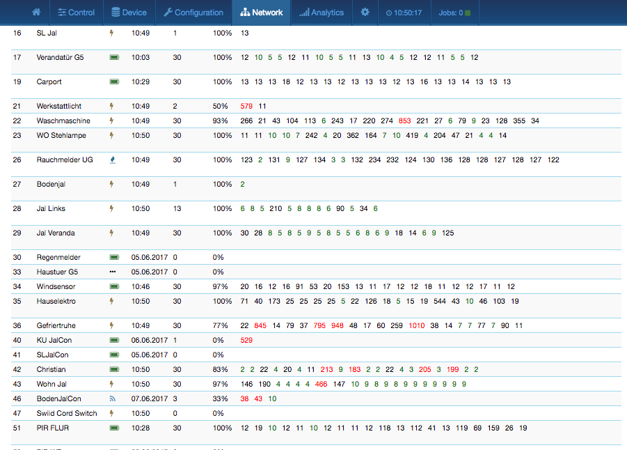
The Timing tab in Figure 7.29 shows some very valuable timing information of communications between the controller and other devices. All other devices the controller has communicated with are shown in a list. The number of packets and the percentage of successful communication are shown. This can give an indication about the stability of the communication link between the controller and this device. On the right-hand side, the timing delay of each communication is shown and color-coded. A red number indicates that this communication finally failed. A communication without rerouting attempts as shown as green and a rerouting attempt is coded in black. The fact that a communication failed (red) may indicate that there is a severe problem in the network or in the device. It is however also possible that a battery-operated device just went back to sleep too fast. Z-Wave professionals can read a lot out of this timing information particularly when combined with the routing table. Please refer to Chapter 8 for more details on troubleshooting Z-Wave networks.
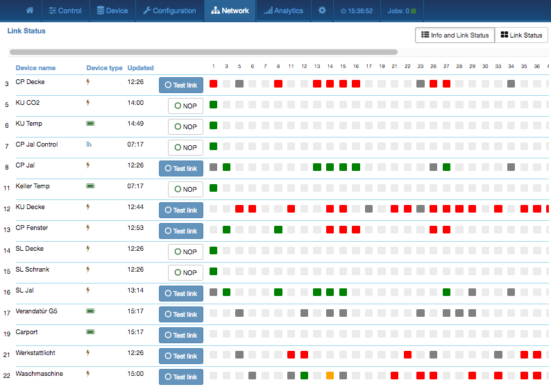
The link status map, as shown in Figure 7.30, summarizes the device-specific link status information from the configuration sections.
The following colors are used:
The links from one device can be retested using the Test link button. However, please keep in mind that this process may take several minutes to complete. For devices that do not offer a link status function in their firmware, there is a simple connection test to the Z-Way controller using a “NOP.’’ Please note that this function does not test a direct wireless connection but the route to the controller only.
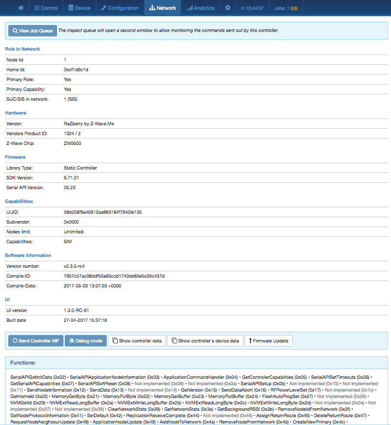
This menu item as shown in Figure 7.31 provides some internal and very technical information about the Z-Way controller software, hardware, and firmware. The different submenu items are self-explaining.
Some buttons allow special maintenance functions:
The last block of the dialog shows the availability of the function calls on the serial API between the Z-Wave transceiver and Z-Way. “Not implemented’’ means that Z-Way is either not knowing about the function indicated by the function ID or does not make any use of it. A red function call ID or name indicated that Z-Way can use this function, but the transceiver’s firmware did not report to offer this service.
Annex ![[*]](crossref.png) gives a full overview of the Functions used and supported by Z-Way.
gives a full overview of the Functions used and supported by Z-Way.
Z-Wave protocol defines a minimal level of interoperability via Basic Command Class. Most devices do act on Basic Set commands mapping it to Switch Binary Set or Thermostat Mode Set or some other. Z-Way is able to control other devices using speical Command Classes or using Basic Set.
Z-Way is handling incoming Basic Set and creates a virtual device that reflects the state of the last Basic Set command recieved. This allows to work with old devices that do not send Reports or Central Scene Notification to the LifeLine association group. Z-Way is ignoring Basic Get commands.
Z-Way supports both Security S2 and Security S0 protocols and implements very strict security rules. See Table 7.1 for more information.
The analytics menu offers functions to troubleshoot a Z-Wave network. Details about the dialogs are provided in Chapter 8.
The setup dialog offers various options to adapt the behavior of the Z-WAVE EXPERT USER INTERFACE :
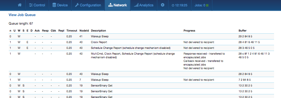
The job queue, as shown in Figure 7.32, offers some deep insight into the dynamics of the controller software. It visualizes the (wireless) task execution of the system. Every communication attempt of the controller is queued and then handed over to the Z-Wave chip for execution. The list shows the jobs pending and the jobs that are completed or failed.
A legend informs about the meaning of the different flags n, U, D, E, S, and W. The timeout
value counts back from 20 seconds once the job was sent. Even when it is completed, the
job will stay in the queue marked as done (D) for some more time to allow inspection. The
target node ID, a description of the communication message, information about the process,
and the real bytes of the message are shown as well.